
HIGH RESOLUTION WINDS (NWC/GEO-HRW)
Updated description including developments for NWC/GEO-HRW v7.0
(released inside NWC/GEO v2025 (vMTG) in June 2025), with examples.
Table of contents
1. Goal of NWC/GEO-HRW
2. Summary description of NWC/GEO-HRW
3. Description of NWC/GEO-HRW inputs
4. Description of NWC/GEO-HRW outputs
5. Examples of NWC/GEO-HRW output visualization
Access to “Algorithm Theoretical Basis Document for the Wind product processors of the NWC/GEO (HRW v7.0)” for a detailed description
1. Goal of NWC/GEO-HRW
NWC/GEO-HRW aims to provide detailed sets of Winds (Atmospheric Motion Vectors, AMVs) and Trajectories from:
- Up to seven MSG-1·4/SEVIRI satellite channels (HRVIS, VIS06, VIS08, IR108, IR120, WV062 and WV073).
- Up to six MTG-I1/FCI satellite channels (VIS06, VIS08, IR105, IR123, WV063 and WV073).
- Up to six Himawari-8·9/AHI satellite channels (VIS06, VIS08, IR112, WV062, WV069 and WV073).
- Up to six GOES-16·19/ABI satellite channels (VIS06, VIS08, IR112, WV062, WV070 and WV074).
The AMVs and Trajectories are calculated through the displacement of cloudiness features in successive images from all these channels, and of humidity features in successive images from the water vapour channels. The AMVs and Trajectories can be calculated 24 hours a day, considering:
- 15 minute image cycles ("Nominal scan mode") or 5 minute image cycles ("Rapid scan mode") with MSG-1·4 satellites.
- 10 minute full-disk image cycles with MTG-I1, Himawari-8·9 and GOES-16·19 satellites.
The product includes pressure level information and a quality control flagging, giving an indication of its error in probabilistic terms. It has been developed by AEMET (the Spanish National Weather Service) in the framework of the EUMETSAT's "Satellite Application Facility on support to Nowcasting and Very short range forecasting" (NWCSAF).
The AMVs and Trajectories can be calculated for up to two different scales at the same time: "Basic scale" and "Detailed scale". The corresponding dimension of the tracers to be tracked can be defined by the user, with a default value of 24 pixels for the "Basic scale" and 12 pixels for the "Detailed scale". Many other processing parameters can also be configured, in particular the region and the satellite channels to be processed for the AMV calculation.
This product can be useful in near real time applications including:
- Nowcasting: Watch and warning of dangerous strong wind situations; Monitoring of the general flow, of convergence and divergence at low and high levels; Monitoring of small scale circulation and wind singularities.
- Forecasting applications: Assimilation of HRW outputs in NWP models, or in applications where the observed wind or the observed displacement of atmospheric features is needed.
Several different HRW outputs (as BUFR or netCDF bulletins) are provided for the calculated winds and trajectories, with a level 2 of processing. A level 3 of processing (as a grid interpolation of the winds or a meteorological analysis based on the data) is not included.
2. Summary description of NWC/GEO-HRW
Eight different steps are considered in the processing of NWC/GEO-HRW:
1. Initialization of data: next matrices are read or calculated for the start of the processing, by the NWC/GEO NWCLIB library, for the running slot and region in which NWC/GEO-HRW is calculated:
- Normalized reflectances for the MSG-1·4, MTG-I1, Himawari-8·9 or GOES-16·19 visible channel images, and brightness temperatures for the MSG-1·4, MTG-I1, Himawari-8·9 or GOES-16·19 infrared and water vapour channel images.
- Latitude, longitude, solar and satellite angle matrices.
- Temperature, wind components and geopotential profiles, and surface pressure fields from NWP data.
- NWC/GEO Cloud type (CT), Cloud top temperature and height (CTTH) and Cloud microphysics (CMIC) outputs (if so configured, as in the default configuration, for a better AMV and Trajectory height assignment).
2. Tracer determination: Two methods are used consecutively:
- Gradient method: with a fast and efficient search of well defined cloud edges.
- Tracer characteristics method: which covers holes in the search of tracers with "Gradient method", with a longer but still reasonable computing time. Two different tests are run based on finding brightness differences inside the tracer, and finding a well defined shape of the feature to be tracked, to avoid too linear elements.
An option inside the HRW algorithm process permits that new tracer centres for the running cycle are defined at the final locations of AMVs calculated for the previous cycle. This way, a set of “Persistent tracers” can be successively tracked in consecutive images, and “Trajectories” are defined through the progressive positions of these tracers throughout the time.
3. Tracer tracking and Wind calculation: One of two well known methods can be used for this process:
- Euclidean distance.
- Cross correlation (default option).
The tracking area in which tracers from a previous image are looked for in the current image, can be defined through the extrapolation of the linearly interpolated NWP wind guess for a quicker running of the algorithm. Nevertheless, this option is not used as default one to reduce the dependence from the NWP winds. The best three tracking centres are kept, from which one is taken at the "Quality Control step".
A “mixed calculation method” is also available since NWC/GEO-HRW v6.0 (v2018), considering at the same time short and long time intervals, through which the tracking process is verified in short time intervals, but the AMVs are calculated considering displacements in long time intervals. This process is useful for the calculation of AMVs with high resolution images, and to improve the quality of the calculated AMVs. However, this option is not used in the default configuration.
4. Height assignment: Two different methods can be used:
- Brightness temperature interpolation method: calculates the cloud top pressure and cloud base pressure, interpolating the brightness temperature of the corresponding satellite channel (or MSG-1·4/IR108, MTG-I1/IR105, Himawari-8·9/IR112, GOES-16·19/IR112 channel in the case of visible channels) to a NWP vertical temperature profile. Then, the AMV/Trajectory pressure is defined through one of these two values, taking into account the cloud type related to the tracer.
- Cross Correlation Contribution (CCC) method (default option): defines the AMV/Trajectory pressure, considering only the pressure of the pixels contributing most to the image correlation (which is available only for "Cross correlation" tracking and if NWC/GEO-CT and CTTH outputs are available). A correction of the pressure level for cloudy AMVs/Trajectories is also implemented, considering the AMV/Trajectory Liquid water path/Ice water path (obtained from the corresponding NWC/GEO-CMIC output, and related to the depth of the cloud which is being tracked).
5. Quality Control: the “Quality Indicator method”, developed for the AMV calculation at EUMETSAT/MPEF, has been adapted for NWC/GEO-HRW. Several consistency tests are if possible computed, considering:
- Temporal consistency test: vector consistency with neighbour AMVs in the previous slot.
- Spatial consistency test: vector consistency with neighbour AMVs in the same slot.
- Forecast consistency test: vector consistency with the NWP forecast wind in the same slot and location.
- Two scale consistency test (only for the “Detailed scale”): vector consistency with simultaneous neighbour AMVs from the “Basic scale” in the same slot.
Three individual “Quality Indices” are calculated for each AMV/Trajectory, considering the normalized statistical fitting functions described by the method and the weighted sum of the partial consistency tests:
- Quality Index with forecast (QIF): Quality index including the forecast consistency test.
- Quality Index without forecast (QINF): Quality index excluding the forecast consistency test.
- Common Quality Index (QIC): defined through a common calculation module to be used by all AMV producing centres. The "Common Quality Index" has shown to provide a real skill in filtering AMVs from different AMV algorithms, for a better consistency.
6. Orographic Flag: an “Orographic flag” is also calculated, related to the detection of land tracers, and tracers blocked by orography or related to orographic waves (for which the AMVs/Trajectories are not displacing with the corresponding atmospheric flow), with next possible values:
- 1: AMV wrongly located below the corresponding surface pressure (basically due to microphysics corrections in the AMV pressure). These AMVs are always skipped.
- 2: Very important orographic influence at the current location of the AMV.
- 3: Less important orographic influence at the current location of the AMV.
- 4: Very important orographic influence at any previous location of the AMV.
- 5: Less important orographic influence at any previous location of the AMV.
- 6: No orographic influence has been found at any current or previous position of the AMV.
In the default configuration, all AMVs/Trajectories with any orographic influence are skipped.
7. AMV Selection: a comparison is made among all AMVs calculated for the same tracer, when more than an AMV has been calculated, for the final definition of the AMV related to that tracer (only one AMV per tracer can be kept). This comparison is made considering the behaviour of each one of those AMVs for each one of the following criteria:
- From the AMV calculation process: tracking correlation.
- From the Quality control process: temporal, spatial and forecast consistency tests; two scale consistency test also for the “Detailed scale”.
- From the Orographic flag process: orographic flag.
Possible test values for each case are:
- 3: When the AMV is the best of all for the same tracer for the corresponding criterion.
- 2: When the AMV is slightly worse than other AMVs for the same tracer for the corresponding criterion.
- 1: When the AMV is rather worse than other AMVs for the same tracer for the corresponding criterion.
- 0: When the comparison could not be defined for the given AMV.
The AMV selection is based on the AMV with the best comparison tests. In case of draw, the AMV with the best forecast consistency test is selected, or else the AMV with the best tracking correlation.
8. Autovalidation of AMVs: considering requests from the users, since NWC/GEO-HRW v6.0 (v2018) the process is able to calculate validation statistics for the AMVs with the algorithm itself, using as reference NWP forecast winds (in real time or reprocessing processes) or NWP analysis winds (in reprocessing processes).
The validation statistics are written for each running slot in a specific file S_NWC_HRW-STAT_*.txt, including information per channel, per level or as a whole on the number of AMVs (NC), the mean wind speed (SPD), the normalized bias (NBIAS), the normalized mean vector difference (NMVD), and the normalized root mean square difference (NRMSVD) with respect to the reference NWP forecast or analysis winds.
The reference NWP wind at the AMV level and the best fit pressure level, and the vector differences with both, can also be calculated and stored in the AMV output for further processing and research.
3. Description of NWC/GEO-HRW inputs
- NWC/GEO configuration files: HRW Model Configuration file (*.cfm) and Region Configuration file (*.cfg).
- MSG-1·4, MTG-I1, Himawari-8·9 or GOES-16·19 satellite data: Full Resolution MSG-1·4/HRIT, MTG-I1/FCI, Himawari-8·9/(HSD or EHH) or GOES-16·19/NetCDF original image files, with brightness temperatures for the infrared and water vapour channels to be used and reflectances for the visible channels to be used, for the working region, for the current and previous slot. MSG-1·4 and GOES-16·19 satellite data are processed directly, but MTG-I1 and Himawari-8·9 need first to be converted to a specific FSD NetCDF format defined by NWC/GEO software with the provided $SAFNWC/bin/start_nwcsdi daemon.
- NWP data: Temperature profiles and longitudinal and latitudinal component wind profiles for as many as possible of the following pressure levels: 1000, 950, 925, 900, 850, 800, 700, 600, 500, 400, 300, 250, 200, 150, 100, 70, 50, 30, 20, 10, 7, 5, 3, 2, 1 hPa. Also geopotential profiles in case the Parallax correction or the Orographic flag is calculated. Also surface pressure fields in case the Orographic flag is calculated.
- NWC/GEO-Cloud Type (CT) and Cloud Top Temperature and Height (CTTH) output for the working region and slot (as in the default configuration, for a better height assignment).
- NWC/GEO-Cloud Microphysics (CMIC) output for the working region and slot (as in the default configuration, for a microphysics correction of the AMV pressure level).
- List of Tracers, Predecessor winds and Trajectories calculated at the previous slot (in case they are available).
4. Description of NWC/GEO-HRW outputs
Depending on configuration, AMVs and Trajectories are provided in the form of BUFR or NetCDF bulletins, considering separately each processed region and each tracer scale used (“Basic scale” and “Detailed scale”). The different options for the HRW outputs are:
1. Two different HRW AMV BUFR output formats:
- One similar to the format used by all previous versions of NWC/GEO-HRW (named S_NWC_HRW-WIND_*.bufr). This case is in the default option for NWC-GEO/HRW. Additionally in this case, if trajectories are calculated, an additional BUFR bulletin (named S_NWC_HRW-TRAJ_*.bufr) is also provided with the content of the corresponding Trajectories.
- Other one equivalent to the new format ("sequence 310077") defined by the IWWG/International Winds Working Group, used by AMV bulletins distributed by all AMV centres through the WMO Global Telecommunications System (named S_NWC_HRW-WINDIWWG_*.bufr).
2. Two HRW NetCDF bulletins, providing information for both AMVs and Trajectories (named respectively S_NWC_HRW_*.nc and S_NWC_HRW-TRAJ_*.nc). In NWC/GEO-HRW v7.0, the structure of the netCDF outputs has changed, is “CF compliant” and easier to process (following the recommendations from NWCSAF users). This case is also in the default option for NWC-GEO/HRW.
For example, the content of the first BUFR bulletin format includes next parameters:
General processing indicators:
- Satellite identifier.
- Generating centre and application.
- Wind computation method.
- Origin of first guess.
- Satellite instrument used.
- Satellite channel central frequency and width.
- Year, month, day, hour, minute of final image.
- Time increment from initial to final image.
- Satellite cycle of final image.
- Quality control characteristics.
- Horizontal and vertical tracer size in pixels.
Processing indicators for each AMV/Trajectory sector:
- AMV/Trajectory identifier.
- Predecessor AMV identifier and Number of Trajectory sectors (if any, with option calculating “Persistent tracers”).
- Horizontal and vertical tracer size in metres.
- Tracer tracking method (“Euclidean distance” or “Cross correlation”).
- Initial latitude and longitude.
- Latitude and longitude increments.
- Wind direction and speed.
- Wind temperature and pressure level.
- Quality indices (QIF, QINF, QIC).
- Type of tracer (Basic tracer; Detailed tracer related to a wide basic tracer; Detailed tracer related to a narrow basic tracer; Detailed tracer unrelated to a basic tracer).
- Type of tracer (Cloudy or Clear air tracer) and Height assignment method used.
- Number of AMVs computed for the tracer (1 to 3).
- Correlation and Quality tests: which or the partial QI consistency tests (two scale, temporal, spatial, forecast, orographic test) have been applied, and in case several AMVs were calculated for the tracer, if the selected one is better, slightly worse or rather worse than the other AMVs for the same tracer for the considered test.
- Number of NWP levels used.
- Number of predecessor AMVs.
- Orographic flag.
- Cloud type.
- MSG-1·4, MTG-I1, Himawari-8·9 or GOES-16·19 satellite channel used.
- Correlation (if “Cross correlation” is used for the Tracer tracking).
- Pressure error (if “CCC method” is used for the Height assignment).
- Pressure correction (if “CCC method” is used for the Height assignment).
- Validation NWP reference wind at AMV level: direction, speed, direction difference and speed difference.
- Validation NWP reference wind at best fit pressure level: direction, speed, direction difference and speed difference.
- Validation NWP best fit pressure level.
- Validation flag (validation against NWP analysis or forecast).
5. Examples of NWC-GEO/HRW output visualization
Four different NWC/GEO-HRW configuration files (*.cfm) have been defined as default option for the running, repectively for use with MSG-1·4 satellites, MTG-I1 satellite, Himawari-8·9 satellites, and GOES-16·19 satellites. All of them are named safnwc_HRW.cfm, and are located in the corresponding $SAFNWC/config subdirectories related to each satellite configuration.
Next figures show the AMV output of NWC/GEO-HRW for specific examples with these satellites and configurations, in which NWC/GEO-HRW has been run with MSG-2 and MTG-I1 satellites in the “European and Mediterranean region”, with Himawari-9 satellite in the "China/Korea/Japan region", and with GOES-16 satellite in the “Continental United States region”.
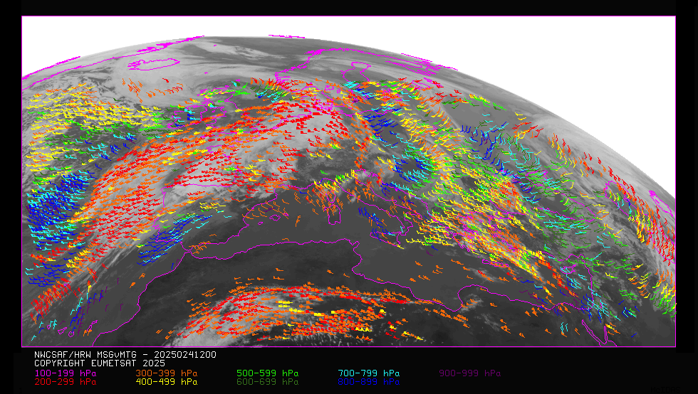
NWC/GEO-HRW v2025 (vMTG) Basic AMVs for “European and Mediterranean region“ (MSG-2, 24 January 2025, 12:00 UTC).
Colours based on the AMV pressure
NWC/GEO-HRW v2025 (vMTG) Basic AMVs for “European and Mediterranean region“ (MTG-I1, 24 January 2025, 12:00 UTC).
Colours based on the AMV pressure
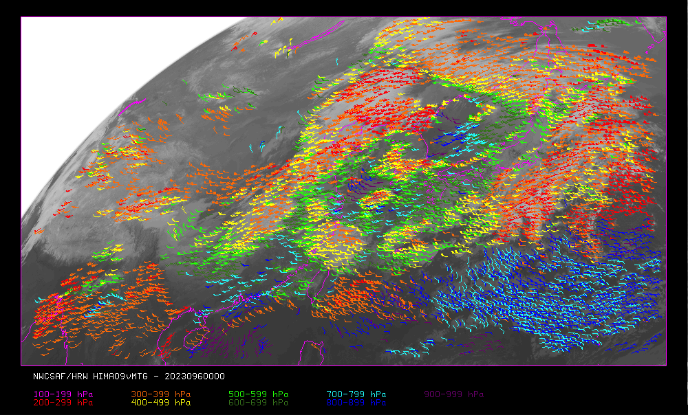
NWC/GEO-HRW v2025 (vMTG) Basic AMVs for “China/Korea/Japan region“ (Himawari-9, 6 April 2023, 00:00 UTC).
Colours based on the AMV pressure
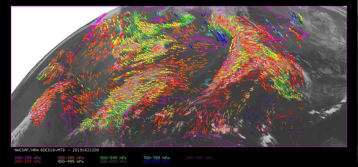
NWC/GEO-HRW v2025 (vMTG) Basic AMVs for “Continental United States region“ (GOES-16, 11 June 2019, 12:00 UTC).
Colours based on the AMV pressure